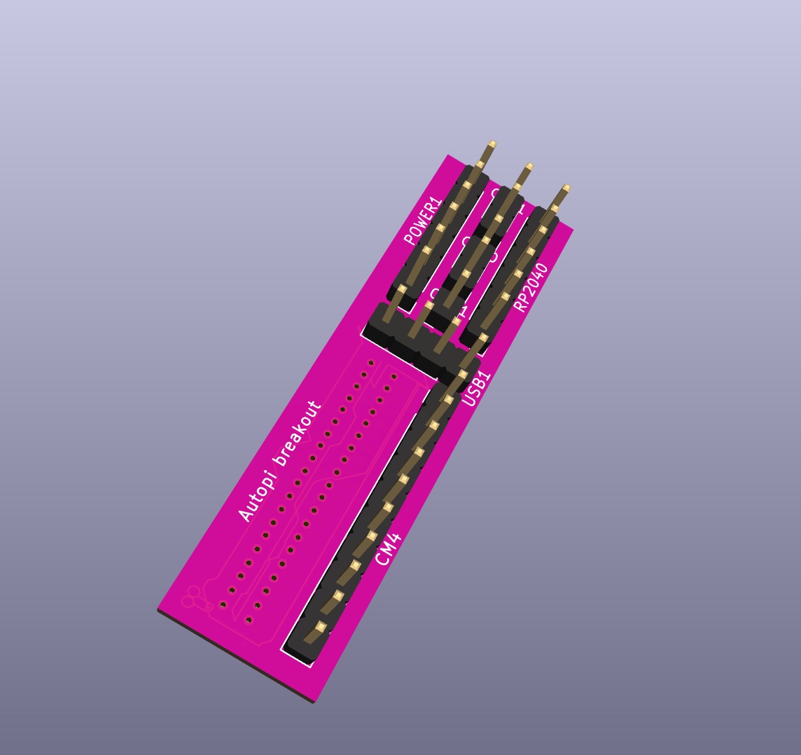
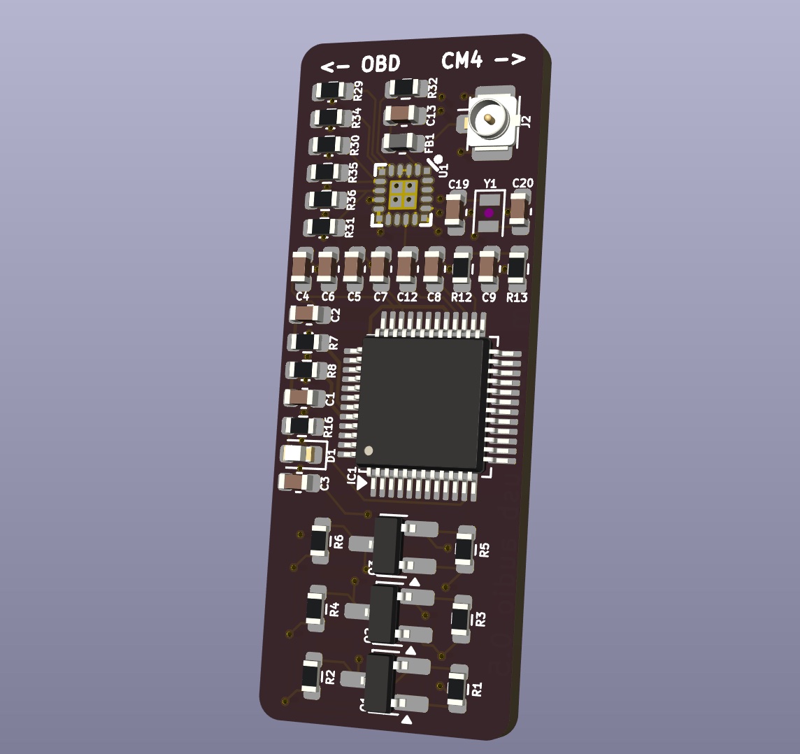
Hi all, wanted to share a couple HAT board designs. I (hastily) made them to help me with another design I have in mind, so the routing is terribad, but I can send the files if you need it.
PS. Does anyone know if the source code for the RP2040 firmware is available? I’ve looked in the Autopi repos on github but couldn’t find it. Was really hoping I wouldn’t have to rewrite the whole firmware to add some extra logic.
Its always great to see development on our internal HAT design, the entire purpose of this.
Unfortunately the source code of the RP2040 on board is not publicly available. But the code on the RP2040 contains ways for you to use it to control the HAT board you designed.
Would be great if you can share more about the usecase of the HAT, then we might be able to point you in the direction of best using the RP2040.
The HAT design I’m currently working on has 3 of these level shifters, an FM radio, and a USB peripheral.
Specifically for the SPM:
OBD_PIN_1 goes to RP2040_GPIO17 (transistor for 12v → 3v3) I’d like to use this pin as input to wake the CM4
OBD_PIN_8 goes to RP2040_GPIO27 I’d like to use this pin for output
OBD_PIN_9 goes to RP2040_GPIO28 I’d like to use this pin for output
The rest of the HAT use CM4’s I2C and USB which works fine, but I can only connect when linux is running. Only these 3 pins that I have to read/write when the CM4 is off. This is also assuming voltage doesn’t change on OBD_PIN_16, so the STN cannot wake up the CM4.
Looks really great. What is the use case of the HAT?
I’m trying to understand why you connected to OBD pins to the RP2040.
The RP2040_GPIO17 pin as already used to wake the CM4, so this is an input pin that you can use exactly to what you intend, to wake up the device.
Both pins RP2040_GPIO27 and RP2040_GPIO28 are defined as output pins in our firmware and can be used how you intend. You can control them from your software on the CM4. This is done using the following commands:
The use case for this HAT is FM radio, and 3 level shifted IO pins. For example, I’d like to wake the CM4 when OBD_PIN_1 is pulled low, then output high (12v) or low on OBD_PIN_8 and OBD_PIN_9 based on conditions.
Primary reasons I’d prefer to control this with the RP2040 instead of the CM4:
Power draw. Having the CM4 running is too much power draw when idle, I’ve seen it kill 12v batteries in couple weeks
It takes too long for linux to boot up, ideally I’d like to toggle output under 1 second
In the future I’d like to add stuff to I2C and talk to them from both RP2040 and CM4.
I understand your reasons for wanting to program the RP2040. It is technically possible to flash your own firmware to the RP2040 using the following command:
However, this will overwrite the existing software on the RP2040.
Would it not be possible for you to make something on your own HAT board, that would turn on the FM radio given a specific signal from the RP2040?
@Peter Thanks. But I was looking for the pinout of the RP2040 on the autopi board. Could you advise which GPIO pins are connected to the CM4 enable pin and LE910Cx enable pin? What about I2C?