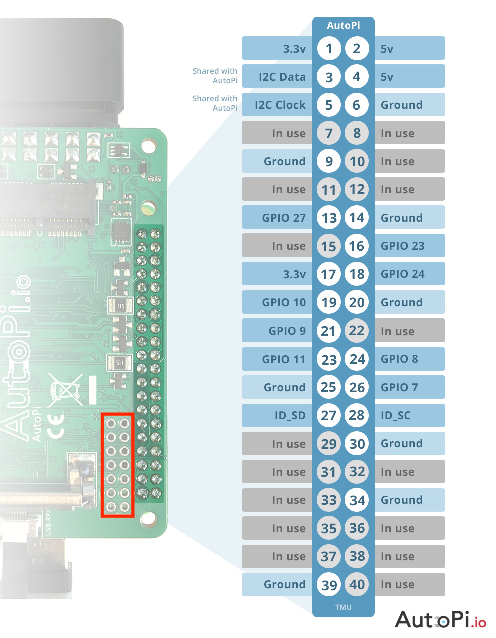
Hi, I just received a 3rd Gen Telematics Unit and am not familiar with the maker terminologies so please pardon me if I make some mistakes. I’m trying to attach a 433 Mhz transmitter module to the GPIO pins and prefer not directly soldering wires to the header. I noticed that there is a 2*7 breakout area on the telematics unit:
Can this breakout area be used as GPIO? So I can either solder wires or headers to this area and attach my modules. If so, what is the pinout? If not, what is the best way to access GPIO on 3rd gen telematics unit?
I had to solder direct to the pin bases. Silly oversight not to have assembled the board with thru-pins so that the other GPIO pins can be accessed easily. From pics I’ve seen, the earlier editions did have thru-pins.
That’s a shame. For now I think the best way is to use a stacking header on TMU. Another possibility is to use a second pi in the network as remote GPIO.